
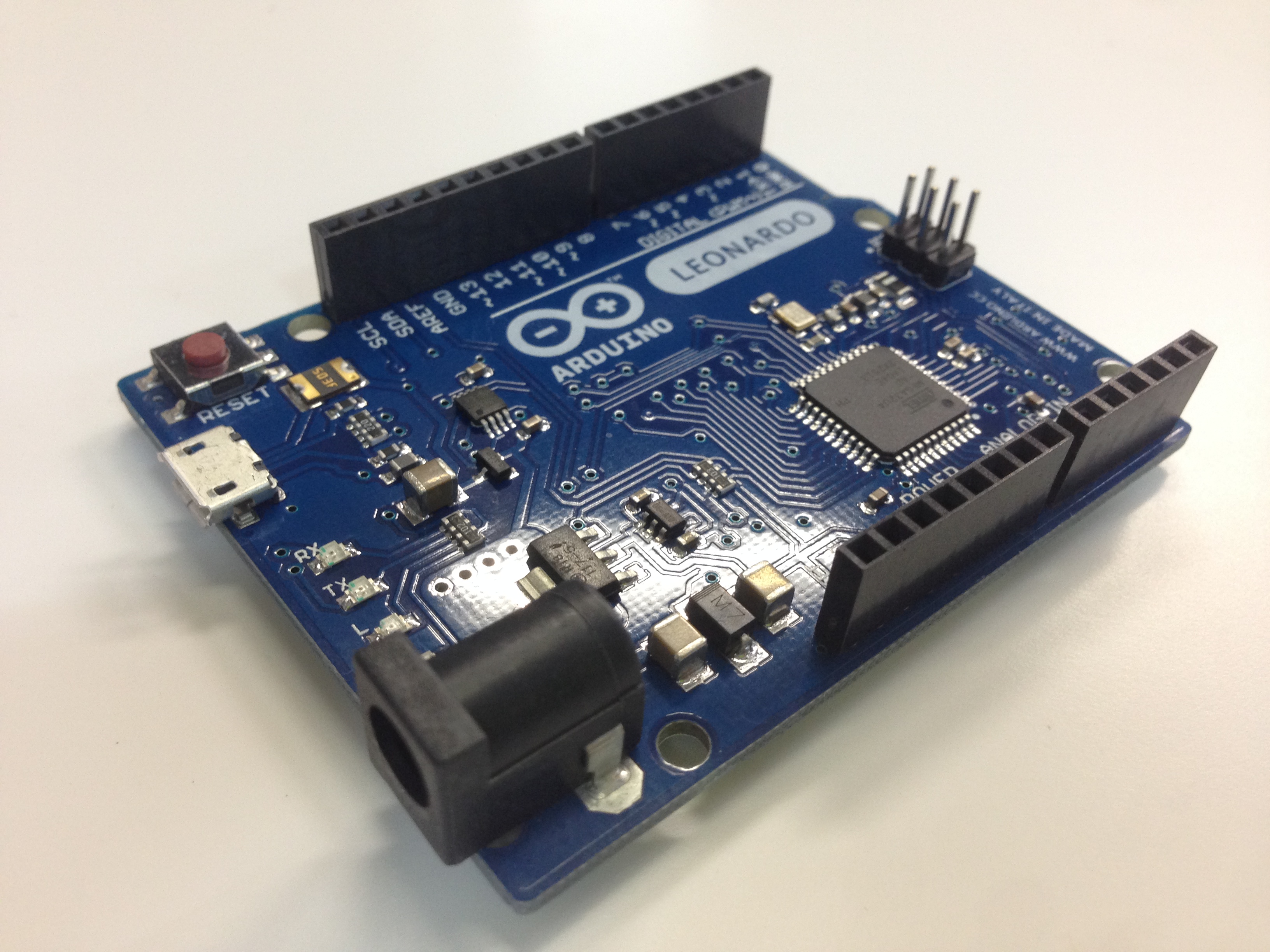
Arduino Leonardo

รายละเอียดสินค้า
มีสาย usb แถมให้ครับ
Summary
| Microcontroller | ATmega32u4 |
| Operating Voltage | 5V |
| Input Voltage (recommended) | 7-12V |
| Input Voltage (limits) | 6-20V |
| Digital I/O Pins | 20 |
| PWM Channels | 7 |
| Analog Input Channels | 12 |
| DC Current per I/O Pin | 40 mA |
| DC Current for 3.3V Pin | 50 mA |
| Flash Memory | 32 KB (ATmega32u4) of which 4 KB used by bootloader |
| SRAM | 2.5 KB (ATmega32u4) |
| EEPROM | 1 KB (ATmega32u4) |
| Clock Speed | 16 MHz |
Input and Output
Each of the 20 digital i/o pins on the Leonardo can be used as an input or output, using pinMode(), digitalWrite(), anddigitalRead() functions. They operate at 5 volts. Each pin can provide or receive a maximum of 40 mA and has an internal pull-up resistor (disconnected by default) of 20-50 kOhms. In addition, some pins have specialized functions:
- Serial: 0 (RX) and 1 (TX). Used to receive (RX) and transmit (TX) TTL serial data using the ATmega32U4 hardware serial capability. Note that on the Leonardo, the Serial class refers to USB (CDC) communication; for TTL serial on pins 0 and 1, use the Serial1class.
- TWI: 2 (SDA) and 3 (SCL). Support TWI communication using the Wire library.
- External Interrupts: 3 (interrupt 0), 2 (interrupt 1), 0 (interrupt 2), 1 (interrupt 3) and 7 (interrupt 4). These pins can be configured to trigger an interrupt on a low value, a rising or falling edge, or a change in value. See the attachInterrupt() function for details.
- PWM: 3, 5, 6, 9, 10, 11, and 13. Provide 8-bit PWM output with the analogWrite() function.
- SPI: on the ICSP header. These pins support SPI communication using the SPI library. Note that the SPI pins are not connected to any of the digital I/O pins as they are on the Uno, They are only available on the ICSP connector. This means that if you have a shield that uses SPI, but does NOT have a 6-pin ICSP connector that connects to the Leonardo's 6-pin ICSP header, the shield will not work.
- LED: 13. There is a built-in LED connected to digital pin 13. When the pin is HIGH value, the LED is on, when the pin is LOW, it's off.
- Analog Inputs: A0-A5, A6 - A11 (on digital pins 4, 6, 8, 9, 10, and 12). The Leonardo has 12 analog inputs, labeled A0 through A11, all of which can also be used as digital i/o. Pins A0-A5 appear in the same locations as on the Uno; inputs A6-A11 are on digital i/o pins 4, 6, 8, 9, 10, and 12 respectively. Each analog input provide 10 bits of resolution (i.e. 1024 different values). By default the analog inputs measure from ground to 5 volts, though is it possible to change the upper end of their range using the AREF pin and the analogReference() function.
There are a couple of other pins on the board:
- AREF. Reference voltage for the analog inputs. Used with analogReference().
- Reset. Bring this line LOW to reset the microcontroller. Typically used to add a reset button to shields which block the one on the board.
See also the mapping between Arduino pins and ATmega32u4 ports.
วิธีการชำระเงิน
สอบถามสินค้าหรือต้องการใบเสนอราคาหรือใบกำกับภาษีโปรดติดต่อทางร้านก่อนสั่งซื้อครับผม
- ติดต่อผ่าน LINE ID : csanthanaboun
- เบอร์โทร 0909761799
ชำระเงินผ่านธนาคาร
ชำระเงินด้วยการ Scan QR


นาย ชาติไทย สันธนะบูรณ์
090-xxxxxx-9
Accept All Banks | รับเงินได้จากทุกธนาคาร
ระบบสมาชิก


สินค้าในตะกร้า ({{total_num}} รายการ)

ขออภัย ขณะนี้ยังไม่มีสินค้าในตะกร้า
ราคาสินค้าทั้งหมด
฿ {{price_format(total_price)}}
- ฿ {{price_format(discount.price)}}
ราคาสินค้าทั้งหมด
{{total_quantity}} ชิ้น
฿ {{price_format(after_product_price)}}
ราคาไม่รวมค่าจัดส่ง
➜ เลือกซื้อสินค้าเพิ่ม